Mosfet Upgrade - Wanhao Duplicator i3 v2.1
Hey there makers!
Today i decided to do the mosfet upgrade to my duplicator i3, its been on my to-do list for a while but i have some 24+ hour prints to do very soon, so i decided to add this safety feature before i did the long prints where i'll be leaving the printer unattended for several hours at a time.
Just as a point, i consider this a must have safety feature for ANY 3d printer. This isnt specific to just the wanhao duplicator i3, any printer with a heated bed should have a mosfet to take the load from the main board. They are easy to add in and inexpensive for the safety they provide.
Infact, on the Wanhao Duplicator i3 its a failure common failure. The connectors on the main board for the hot bed are cheap and not rated for the current load they see. Theres been numerous reports of these shorting out and damaging the main board, and in severe cases can cause a fire. So for the sake of £10 i consider a mosfet install a must.
Here is the list of items you'll need to buy if you dont already have them, i'll put links to them :)
mosfet
wiring
4 x m3x6 screws/cap head bolts
4 x nylon washers (can get away without)
Mosfet:
This is the mosfet that i used, they can be had for much cheaper from aliexpress or ebay if you dont mind waiting for them.
https://www.amazon.co.uk/gp/product/B01NCYD18Y/ref=oh_aui_detailpage_o01_s01?ie=UTF8&psc=1
Wiring:
I used 16 gauge which is the minimum i'd recommend to use, use 14 gauge if your buying the wire for the mosfet install
16 gauge wire
https://www.amazon.co.uk/gp/product/B01FG2OVJW/ref=oh_aui_detailpage_o04_s00?ie=UTF8&psc=1
14 gauge wire
https://www.amazon.co.uk/d/DIY-Tools/YCNK-12Feet-Gauge-Super-Flexible-Silicone-Rubber/B01FG2OUE8/ref=pd_bxgy_60_2?_encoding=UTF8&psc=1&refRID=5XGY52633XYNESDSSZEQ
Tools i used:
M3 hex allen key
Phillips screwdriver
Flat head screwdriver
precision flat head screwdriver
Wire strippers
Extra's you need
You will need to mount your mosfet somehow, i chose to print a mount which piggybacks onto the standoff's for the main board in the control box. You will use your 4 m3 screws to attach your mosfet to the mount. Thingiverse link below
https://www.thingiverse.com/thing:2295820
Lets get started!
Turn off the power on the back of the control box, and move the printer and control box onto a flat work surface.
First you need to remove the back cover on the control box, this is done by removing 4 x m3 screws around the back of the cover
Be careful moving the back cover around as when i first took the cover off a while ago i unplugged the cover fan by accident. Place this gently to one side, and then place the control box with the bottom facing up
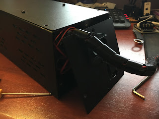
Now, starting from the back of the unit, undo 6 screws along its sides and the center screw at the bottom of the picture.

Once you have removed them all, the cover with the power supply on can slide out of the control box, again be careful not to snag any wires

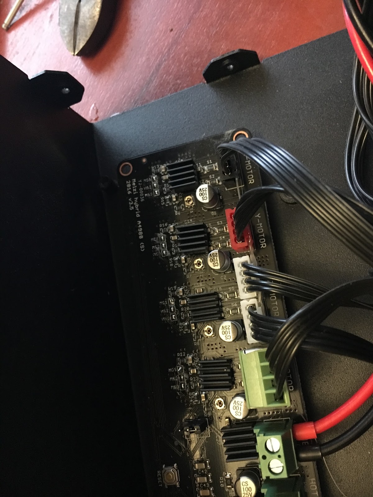
Slide this cover off all the way and place it down carefully to the side with the power supply facing up. Now, you have the main board exposed and we can get to what we came here to do! Here's what you'll be faced with.

Now you can put your mosfet on the mount you printed off, and screw it into place using some m3 screws or bolts, use nylon washers here if you have them.
Then you'll want to remove the main board from the standoffs, undo the 4 m3 screws in each corner of the board


I also unplugged the ribbon cable for the screen so i didnt snag the cable by accident

Then, push your mosfet mount down onto the main board standoffs. Mine were a nice snug fit and had to pushed on to both standoffs at the same time or it wouldn't fit.

Voila! Mosfet installed and job done!
No, but your not too far off finishing! Put the control board back onto the standoffs and screw down into place. Now we can wire in the mosfet
You see the 2 green connectors above the orange 2? The bottom of these 2 green connectors are for the heated bed of your printer, it says "HOT BED" under the wires.

Now you can either pull the connector out or, because mine had a dab of hot glue on the side and i had no more, you can do it in place.
Start by using a small flat head screwdriver to undo the 2 screws on the connector holding the wires in.

On my mosfet, the wire with the solid line was the posetive, and the broken line was the negative. Check the specs of the mosfet you buy if it is different to the one shown here. (yes, i know i spelled positive incorrectly...)

Strip off a little extra of the wire insulation, and bend the exposed wire end in half to double the thickness, this will help the connector "bite" and hold the wire better.


Then put the positive (longer solid line on cable) into the right hand side of the connector, you can use the connector for the hotend next to it for reference on what it positive and negative, and the negative cable into the left hand side of the connector. Then tighten down the screws to hold them in place making sure the insulation of the wires is not caught in the connector, you want to clamp down on the wire, not the insultion.

Next, take the wire you took out of this connector, and attach them to the + and - to the "BED" terminals on your mosfet, and tighten the terminal screws again checking the wire insulation is not catching the terminals.

Now we need to supply the mosfet with 12v power. This is where the wire you bought (or already have) comes in, cut off a length that reach up and down the control box once, like in the picture below. This should give you enough slack if you need to get into the control box again.

Next strip off 1/2 an inch or 12-15mm of insulation from the wire on both end. On each wire twist the exposed wire and then bend in half like you did earlier to the smaller wire.


Then you can attach one of the red wires ends to the mosfet on the '+' side, and the black wire to the '-' side, like so, and tighten the terminal screws

Now on the Wanhao Duplicator i3 v2.1 there are 2 empty spaces on the power supply, 1 COM and 1 +V. Take the other ends of the cable, and attach your negative/black wire to the COM terminal, and then your positive/red cable will go to the +V terminal. Make sure the insulation of the wires are not clamped and these terminals are screwed down tight on the wire (i went back and re-did my supply side wiring), then go along and tighten all of them to be sure there all snug.


Now you mosfet is installed! Before we put all together, first lets make sure the mosfet actually works. Make sure nothing metal is touching, and plug in your power cable to the back cover, and turn your machine on. After checking to make sure no magical pixie smoke comes out of your control box, tell your bed to heat up to 50 degree's, If you have the same mosfet as me a led on the board lights up to let you know the mosfet is active and sending power to the heatbed.
Then monitor the screen to see if it gets up to temp ok.


If it gets to temp ok and stays there, now tell it to cooldown, and the led light on the mosfet should now turn off.

Now you get to put your control box back together, I like to put some cable ties in to keep the cables tidy but thats up to you.

Follow the process for opening up your control box in reverse to put it back together and your done! Little tip, i start from near the screen when putting the screws back in on the bottom, and work my way to the back 2. It makes lining up the holes a little easier.
Well there you go, my very picture heavy guide to installing a mosfet in your Duplicator i3 v2.1, but it should be a similar process for most 3d printers. I hope this helps some of you who want to do this mod but think its looks/sounds complicated. Its a very simple mod, and what i consider a MUST have on any 3d printer. As its another layer of security to stop your printer catching fire when you leave in unattended on longer prints, or for printing with abs, petg ect. that requires hot bed temps of 90+
Thanks for reading everyone, hope you enjoying it
Keep safe,
ThatNerd.
Twitter: @ThatNerdChannel
Youtube: https://www.youtube.com/channel/UCGUusf62uOq2N7xUoLtLq5A
Today i decided to do the mosfet upgrade to my duplicator i3, its been on my to-do list for a while but i have some 24+ hour prints to do very soon, so i decided to add this safety feature before i did the long prints where i'll be leaving the printer unattended for several hours at a time.
Just as a point, i consider this a must have safety feature for ANY 3d printer. This isnt specific to just the wanhao duplicator i3, any printer with a heated bed should have a mosfet to take the load from the main board. They are easy to add in and inexpensive for the safety they provide.
Infact, on the Wanhao Duplicator i3 its a failure common failure. The connectors on the main board for the hot bed are cheap and not rated for the current load they see. Theres been numerous reports of these shorting out and damaging the main board, and in severe cases can cause a fire. So for the sake of £10 i consider a mosfet install a must.
Here is the list of items you'll need to buy if you dont already have them, i'll put links to them :)
mosfet
wiring
4 x m3x6 screws/cap head bolts
4 x nylon washers (can get away without)
Mosfet:
This is the mosfet that i used, they can be had for much cheaper from aliexpress or ebay if you dont mind waiting for them.
https://www.amazon.co.uk/gp/product/B01NCYD18Y/ref=oh_aui_detailpage_o01_s01?ie=UTF8&psc=1
Wiring:
I used 16 gauge which is the minimum i'd recommend to use, use 14 gauge if your buying the wire for the mosfet install
16 gauge wire
https://www.amazon.co.uk/gp/product/B01FG2OVJW/ref=oh_aui_detailpage_o04_s00?ie=UTF8&psc=1
14 gauge wire
https://www.amazon.co.uk/d/DIY-Tools/YCNK-12Feet-Gauge-Super-Flexible-Silicone-Rubber/B01FG2OUE8/ref=pd_bxgy_60_2?_encoding=UTF8&psc=1&refRID=5XGY52633XYNESDSSZEQ
Tools i used:
M3 hex allen key
Phillips screwdriver
Flat head screwdriver
precision flat head screwdriver
Wire strippers
Extra's you need
You will need to mount your mosfet somehow, i chose to print a mount which piggybacks onto the standoff's for the main board in the control box. You will use your 4 m3 screws to attach your mosfet to the mount. Thingiverse link below
https://www.thingiverse.com/thing:2295820
Lets get started!
Turn off the power on the back of the control box, and move the printer and control box onto a flat work surface.
First you need to remove the back cover on the control box, this is done by removing 4 x m3 screws around the back of the cover

Be careful moving the back cover around as when i first took the cover off a while ago i unplugged the cover fan by accident. Place this gently to one side, and then place the control box with the bottom facing up
Now, starting from the back of the unit, undo 6 screws along its sides and the center screw at the bottom of the picture.

Once you have removed them all, the cover with the power supply on can slide out of the control box, again be careful not to snag any wires

Slide this cover off all the way and place it down carefully to the side with the power supply facing up. Now, you have the main board exposed and we can get to what we came here to do! Here's what you'll be faced with.

Now you can put your mosfet on the mount you printed off, and screw it into place using some m3 screws or bolts, use nylon washers here if you have them.
Then you'll want to remove the main board from the standoffs, undo the 4 m3 screws in each corner of the board

I also unplugged the ribbon cable for the screen so i didnt snag the cable by accident

Then, push your mosfet mount down onto the main board standoffs. Mine were a nice snug fit and had to pushed on to both standoffs at the same time or it wouldn't fit.

Voila! Mosfet installed and job done!
No, but your not too far off finishing! Put the control board back onto the standoffs and screw down into place. Now we can wire in the mosfet
You see the 2 green connectors above the orange 2? The bottom of these 2 green connectors are for the heated bed of your printer, it says "HOT BED" under the wires.

Now you can either pull the connector out or, because mine had a dab of hot glue on the side and i had no more, you can do it in place.
Start by using a small flat head screwdriver to undo the 2 screws on the connector holding the wires in.

On my mosfet, the wire with the solid line was the posetive, and the broken line was the negative. Check the specs of the mosfet you buy if it is different to the one shown here. (yes, i know i spelled positive incorrectly...)

Strip off a little extra of the wire insulation, and bend the exposed wire end in half to double the thickness, this will help the connector "bite" and hold the wire better.


Then put the positive (longer solid line on cable) into the right hand side of the connector, you can use the connector for the hotend next to it for reference on what it positive and negative, and the negative cable into the left hand side of the connector. Then tighten down the screws to hold them in place making sure the insulation of the wires is not caught in the connector, you want to clamp down on the wire, not the insultion.

Next, take the wire you took out of this connector, and attach them to the + and - to the "BED" terminals on your mosfet, and tighten the terminal screws again checking the wire insulation is not catching the terminals.

Now we need to supply the mosfet with 12v power. This is where the wire you bought (or already have) comes in, cut off a length that reach up and down the control box once, like in the picture below. This should give you enough slack if you need to get into the control box again.

Next strip off 1/2 an inch or 12-15mm of insulation from the wire on both end. On each wire twist the exposed wire and then bend in half like you did earlier to the smaller wire.


Then you can attach one of the red wires ends to the mosfet on the '+' side, and the black wire to the '-' side, like so, and tighten the terminal screws

Now on the Wanhao Duplicator i3 v2.1 there are 2 empty spaces on the power supply, 1 COM and 1 +V. Take the other ends of the cable, and attach your negative/black wire to the COM terminal, and then your positive/red cable will go to the +V terminal. Make sure the insulation of the wires are not clamped and these terminals are screwed down tight on the wire (i went back and re-did my supply side wiring), then go along and tighten all of them to be sure there all snug.


Now you mosfet is installed! Before we put all together, first lets make sure the mosfet actually works. Make sure nothing metal is touching, and plug in your power cable to the back cover, and turn your machine on. After checking to make sure no magical pixie smoke comes out of your control box, tell your bed to heat up to 50 degree's, If you have the same mosfet as me a led on the board lights up to let you know the mosfet is active and sending power to the heatbed.
Then monitor the screen to see if it gets up to temp ok.


If it gets to temp ok and stays there, now tell it to cooldown, and the led light on the mosfet should now turn off.

Now you get to put your control box back together, I like to put some cable ties in to keep the cables tidy but thats up to you.

Follow the process for opening up your control box in reverse to put it back together and your done! Little tip, i start from near the screen when putting the screws back in on the bottom, and work my way to the back 2. It makes lining up the holes a little easier.
Well there you go, my very picture heavy guide to installing a mosfet in your Duplicator i3 v2.1, but it should be a similar process for most 3d printers. I hope this helps some of you who want to do this mod but think its looks/sounds complicated. Its a very simple mod, and what i consider a MUST have on any 3d printer. As its another layer of security to stop your printer catching fire when you leave in unattended on longer prints, or for printing with abs, petg ect. that requires hot bed temps of 90+
Thanks for reading everyone, hope you enjoying it
Keep safe,
ThatNerd.
Twitter: @ThatNerdChannel
Youtube: https://www.youtube.com/channel/UCGUusf62uOq2N7xUoLtLq5A

Thanks, this was very helpful.
ReplyDeleteHey this was really great. Thanks so much man.
ReplyDeleteThank you! Works great!
ReplyDeleteI will be doing this with my Balco printer which is a re branded same one. But I have a question. I also have a Cocoon touch which is the same as a Wanhao Duplicator i3 Plus with touch screen. It's a 24v version instead of a 12v, so will this fix help that one too or is it a 12v fix only?
ReplyDeleteI'm going to answer my own question here. I found that the MOSFET upgrade is a 12-24v item so it will work with both printers.
DeleteBest tutorial I ever found!!!!!!
ReplyDeleteThank you :)
DeleteI have upgraded my Balco with this and all I can say is that it is EXCELLENT! No overheating problems and the original MOSFET doesn't even get warm on the board. A great lifesaver! No more burnt out boards.
ReplyDeleteApologies i didnt see your previous comment. Glad you got to the upgrade, i see it as a must have for printers that use a heated bed. Happy this guide was of some help :)
DeleteSome help is a definite understatement - should be the best help! After waiting for my third burnt out board in less than a year, this is one of the best tweaks I have seen and I can see that a $7 'insurance' item will save hundreds down the line. When I told Balco about the upgrade, they quoted
Delete' The link you provided looks like the modification has been done by someone who understands the science and it gets a successful result. '
So from another technician, it seems that even they think it's a good idea!
Thank you heaps!
Its certainly a very cheap but effective modification to do which will save down time further down the road, not to mention the cost of some printers main boards means you might aswell buy a new printer. Better safe than sorry!
DeleteThank you very much, im glad Balco liked the article. There welcome to direct users to it. I am currently doing this mod on another one of my printers, so i may record a video on the process, as its practically the same process for many, many brands of printers.
Thanks again for the kind words :)
Thanks, I did my MOSFET upgrade guided by your post. Only word of advice: even if you buy same MOSFET as in post, check positive and negative wires for control (mine were switched :)
ReplyDeleteGlad to hear you did the upgrade. Thank you for the advice, Though this shouldn't really matter as the control wire it just a small voltage to turn on the mosfet. It shouldn't matter what phase these wires are in :) (as far as i know)
DeleteThank you for the comment :D
Outstanding job - well written and easy to follow!! My son and I made this switch last night on his Monoprice Select. Thanks for the great instructions and informative pics to guide us along.
ReplyDeleteThank you for the kind words. Happy to hear you got the relay put in, must have safety feature :) Happy printing!
DeleteI have an older model Wanhao I3, the control box is a rectangular shape with no angled LCD screen, and the control board is mounted on it's side instead of the bottom, with the PSU being on the bottom.
ReplyDeleteBecause of this, I don't think the mounting bracket will work for mine, are you aware of a version of that bracket that can be used on the older model Wanhao I3 printers?
Hmm, i am honestly not sure if the bracket would work with a V1 of the Wanhao Di3. The length looks like it would be ok, just a matter of if the locating holes for the bracket line up. Im sure if you search Thingiverse or ask on the Facebook group someone will be able to supply at STL to one that would fit :)
DeleteHappy printing!
Awesome instructions, thank you so much for them. Unfortunately my "HOTBED" terminal fried to the point that its stuck "OPEN" you could say. After following your instructions my MOSFET turns on and just starts heating and won't stop. It seems I have an issue with ground. Can I possibly share the ground with the 12v supply?? Tested the theory with leaving the (+) terminal landed on "HOTBED" (+) and sharing the ground with the "EXTRUDER" only thing is, HOTBED wont turn off when it hits temp. Keeps rising until EXTRUDER makes temp. Any ideas?
ReplyDeleteWell-done instructions, immensely helpful! Thank you!
ReplyDeleteI enthusiastically echo all of the praise for the clarity of your tutorial. Before I ended up here, I suffered through any number of youtube videos which failed to clearly show polarity of the connections and other stuff. Thank you! Any plans to install other mods? tl-smoother or bl-touch auto leveler? Firmware bootloader and upgrade? :-)
ReplyDeleteThanks a lot!!
ReplyDeleteLate to the party, but did the upgrade using your excellent post. Thanks!
ReplyDelete